Overview
Test benches are an important part for testing and demonstrating the various products as well as systems. Mainly test benches in industry are used for testing different products manufactured by the respective organisation, for example HV testing kit, Watt loss test bench, etc. Whereas in educational institute test benches are used to demonstrate and to showcase the different practical experiments to the engineers. Here the most common type of test benches are Wattmeter method testing kits, Balance and unbalance load testing kits, and Motor load testing kits. Under CSR activity Bosch manufactures Test benches for Govt. IT institutes.
Problem Statement
Load Test Bench kit requires various devices like analog & digital meters, current transformers switches and multimeters. For the above requirement we were able to provide all the devices except the Multistep switch for Load addition. Earlier multiple toggle switches were used to turn on the different load bulbs in a stepwise manner to increase the load current. It used to cover a large space of the test bench in comparison to all other devices. Due to this, a special switch was required for the addition of bulb loads in a stepwise manner. This arrangement was done to show the impact of load variation on the current value. The switch should be aesthetically good, easy to operate and safer in operation.
Solution
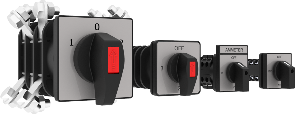
For the above problem, we developed a Multi-step Load addition switch 1 Pole 6 ways. This switch completes the product offering basket required for the test bench kit.
Below table represents the list of products offered by rishabh along with their purpose:
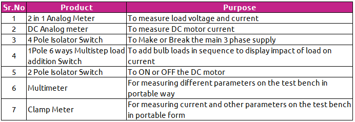
From the below image , we can see that multiple devices are used to measure, monitor and control the different load reading. At first 4 pole MCB is used to protect the system against overload. A 4 pole isolator switch is connected after the MCB for turning ON or OFF electrical supply. Output of the Isolator switch is connected to 3 Multi Step load addition switches with single pole 6 way configuration( R phase to switch 1, Y phase to Switch 2 and B phase to Switch 3). Each switch has 6 output terminals and a single input terminal where respective R, Y and B phases are connected. At each output terminal of the switch, 2 bulbs are connected. So each switch operates 12 bulbs.
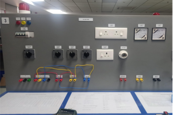
When switching the R phase multi-step switch from OFF to Position 1 ( 45 degree rotation), 2 bulbs will glow. Further, after rotating the switch from position 1 to position 2, another 2 bulbs will glow along with the previous bulbs. Similarly when the switch is at position 6, total 12 bulbs will glow. Like this if all 3 switches are kept at position 6, total 36 bulbs will glow simultaneously. The variation of the load can be observed in the voltage and current reading with the help of analog meters. This is done for the AC section of the test bench.
Similarly for the DC section a 2 pole Isolator Switch is used to turn On and OFF the DC motor. You can see the connection terminals on the test bench where multimeter probes can be connected to view the instantaneous Voltage, current, resistance and continuity parameters.
Benefits
- Single window solution
- Various operations can be performed in a single kit
- Aesthetically looks good
- Provides IP 20 terminal protection
- Long distance visibility
Features
- Compact Size
- Reliable Design
- Quick & Easy Installation
- High Protection Class
- High Mechanical and Electrical Life
- Low contact resistance
Below are some other application areas for Cam Switches
- Distribution Board
- Breaker Panels
- Busbar Coupler Panels
- LV Panels