Overview
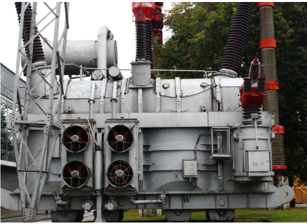
Electrical Transformers are crucial equipment in an AC electrical system. Transformers convert the voltage and current from one level to another level, however constant output of the transformer has to be maintained irrespective of the input upto a certain level. This is an important requirement to ensure power reliability and it is controlled by a Tap Changer (TC) mechanism. Tap changers are mainly of two types no load tap changers (NLTC) which works in a de-energized state before the turn ratio is adjusted and on load tap changers (OLTC) which adjusts turns ratio on a loaded or energized transformer.
Problem Statement
According to conventional methods implemented so far, a separate panel for monitoring the on load tap changer tap position is provided. However, this arrangement cannot either record or transfer the information to remote control centers for controlling and monitoring purposes. Due to the advent of Smart Grids it is essential to implement a centralized supervisory system like a SCADA system which can parameters remotely. Hence, devices are required which can transfer the signals of an OLTC to control room or at least indicate the position of tap.
Solution
Two arrangements of OLTCs used in general are (i) Reactor type OLTC and (ii) High speed resistor type OLTC. In order to obtain regulated voltage at the output of a transformer, OLTCs tend to maintain the system voltage continuously by varying the tap positions on a transformer by control pulses (low or high) from the control circuit. To achieve this, a closed loop control system is required.
Firstly, the current (actual) position of the tap changer has to be identified. Hence a device which could convert mechanical movement to electrical signal is required. Such devices are called transducers. These transducers are used to convert the position of the tap changer to a current output. It converts the measured quantities of resistance into a proportional DC signal.
Dedicated devices like a Tap position indicator or transducer like Rish Con TPT can fulfill this requirement very effectively. Their outputs can be fed to control devices, recorders, RTU or panel indicators. Rish Con TPT comes with an option of two analog outputs which can be programmed for either analog current signal of 0-20 mA or 4 – 20 mA or voltage signals of 0-5V, 1-5V, 0-10 V, 2–10 V used as per applications.
Working
When the load demands high energy supply from the grid, a reduction in voltage supply occurs. During this event the voltage regulatory system identifies voltage reduction and accordingly changes the tap position on the primary side of a transformer. To monitor the position of tapping ,tap position transducer is placed such that it will receive input in terms of resistance i.e. in Ohms and convert the value accordingly to DC analog signals for e.g. 4-20mA. This signal is fed to intelligent electronic devices which then helps in controlling the tap changer as per requirements.
Benefits
- Input measuring range can be programmed using PC, simplifies project planning and engineering
- Electrically isolated analog outputs prevent interference voltage and current. Solves grounding problems in meshed signal networks
- High electric isolation between input and output – 2.3 kV, and power supply versus all other circuits – 3.7 kV.
- Tap position is displayed on front LED display
- Galvanic and optical isolation between power supply, input and outputs

