

Overview
In substations, battery banks are installed in order to provide reliable supply to control circuit breakers and measuring instruments. They are also used as back-up systems at a substation. Back-up systems form an important backbone of any system considering the backup supply and are of very high importance to utilities. The key purpose of the back-up system is to provide power in case of mains failure to peripheral devices such as protective devices and high voltage components allowing safe isolation from electrical faults. Any failure in the backup system may lead to severe consequences to equipment or sometimes the system as a whole. Such failures may also result in interruption and major system disturbances. In substations mostly 110 VDC or 220 VDC battery banks are used.
Problem Statement
Batteries are energy storage devices and are self depreciating. After a period of time, voltage drop across its output increases. It is necessary to monitor this voltage as well as indicate or signalize the system when voltage drop exceeds certain specified limit. Due to the absence of such monitoring systems, substations face challenges regarding false operation of protection devices and unplanned shutdowns.
Present Scenario
In the already installed monitoring system, Analog Panel Meters were used to indicate the battery Voltage, charging / discharging currents. These only sufficed the purpose of an approximate indication. It could not generate any kind of alarm signalling nor had any fault indication or battery check point involved. This needed continuous human supervision, which was a cumbersome activity.
Solution
- It is essential to use an instrument capable of measuring DC voltage and current as an input from batteries
- To cater such needs a relevant product – N30H (Digital Tri-Colour Indicator with Higher DC Voltage / Current Input and various Output Options) was selected
- The solution consisted of multiple models assembled in one panel.
Key highlights of the product
- Tri-colour Display – Programmable in three intervals of the measured value (RED/ ORANGE/ GREEN)
- Relay Outputs – Used for ON /OFF indications
- Analog Outputs (4 to 20 mA or 0- 10 V) – Considered for future monitoring in centralized system
- RS485 Modbus interface – Considered for future monitoring in centralized system
- IP65 Protection
Working
The solution was expected to work in accordance with the conditions specified such that successive triggers to buzzer would be initiated :
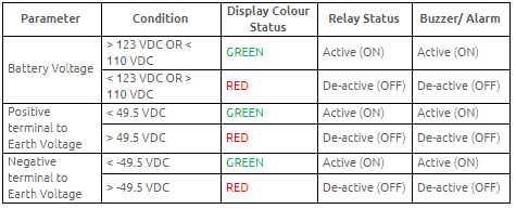
Benefits
- Tri-Colour display indication helping the user to visualize the healthy / unhealthy condition of the system
- Relay outputs to trigger the buzzer over desired levels so as to warn the rise in voltage depreciation
- Provision of analog output & RS485 Modbus port for interface with centralized system
- The solution was provided in a compact panel with easy mounting provision
Application Areas
- Power Stations – Battery backup system
- Data Centres
- Railways
- UPS Industry