Overview
Induction motors are widely used in industries due to their robust construction and operation. The speed of an induction motor is not required to be the same always and this depends on the requirement of the process, unnecessary operation of an induction motor at full speeds demands more energy and hence speed control is essential.
Earlier, conventional methods of speed control were used to adjust the speed of three-phase induction motors but due to the advent of increased availability of power electronics, speed control methods became more diversified. One such control method is using Variable Frequency Drives.
Variable frequency drives or VFDs are now installed in almost every industry ranging from water pump applications to huge machine tool industries. Variable Frequency Drives can regulate the speed of a three-phase induction motor by converting three-phase AC line voltage to a quasi-sinusoidal pulse width modulated (PWM) waveform in which the frequency and voltage level can be varied.
Problem Statement
The voltage applied to the motor terminals by the VFD is a pulse width modulated non-sinusoidal voltage. During fault or abrupt operation of drives it becomes necessary to diagnose the faulty area in the system. Hence, troubleshooting is carried out.
For troubleshooting and maintenance, clamp meters are used by maintenance personnel. Clamp meters have a wide bandwidth, sometimes as high as 20 kHz or more, which allows the meter to respond not only to the fundamental component that the motor really responds to, but also to all of the high frequency components generated by the PWM drive.
Clamp meters are generally not shielded from high frequency noises, this leads to poor measurement performance due to the high noise levels generated by the drive controller. Because of their higher bandwidth and shielding issues, many true RMS meters will display readings as much as 20 to 30 % higher than the true value indicated by the drive controller. In such cases, the personnel has to guess VFD voltage and frequency values.
Solution
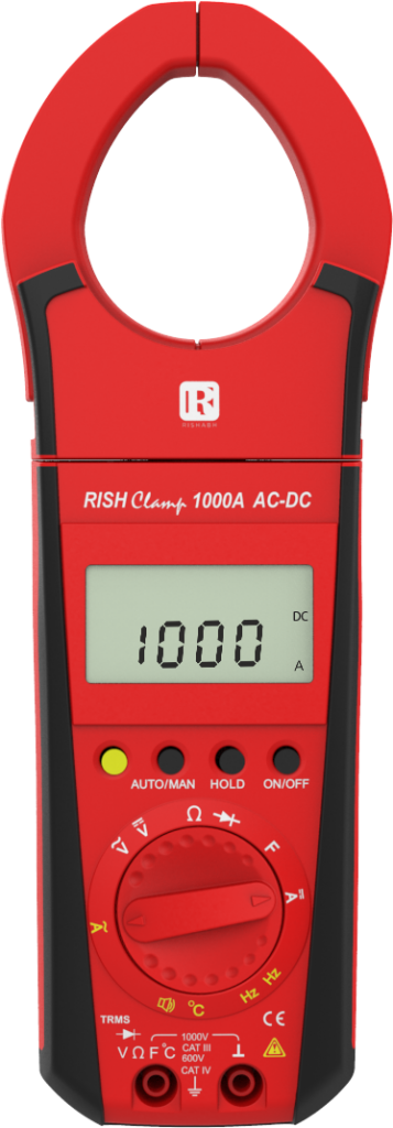
- Rishabh’s RISH Clamp Power 1000A/400A AC/DC is equipped with a selectable function of Low Pass Filter along with a cutoff frequency of 400Hz
- Low Pass Filter allows only low frequency signals to pass unaltered, while attenuating all unwanted signals with frequency range equivalent to that of IGBT’s switching frequency, that tend to superimpose on actual voltage signals.
- LPF mode can be selected by keeping knob on VAC or IAC and press the two keys (as shown above) simultaneously.
- Main display will indicate the actual voltage at the desired frequency.
Low pass filter technology
A low pass filter is a signal filtering circuit that allows only the lower frequency signals to pass and falls under the pass band, obstructing higher frequency signals – stop band. The frequency at which these two bands are distinguished is called cut-off frequency. A simple passive low pass filter (LPF), can be easily made by serially connecting a single resistor with a single capacitor as shown below, the response of the filter depends on the ratings of components selected i.e designing it for a certain cut-off frequency.
Benefits
- Measures voltage accurately without the need of operators guesswork
- Reduces chances of error due to false reading
- Makes fault detection in VFD systems easier
- Unique feature available in clamp meters