Overview
Insulation Resistance (IR) is among the most common tests conducted on industrial motors.
A regular program of testing insulation resistance is always recommended to prevent electrical shocks, assure safety of personnel and equipment, as well as to reduce or eliminate down time.There are several diagnostic tests associated with Insulation Testing. One of such diagnostic tests is Step Voltage test.
Problem Statement
Frequently, electrical shock is experienced from the motor body employed at a certain manufacturing plant. The most common reason is insulation damage. There is a need to ensure the complete insulation between the Live part of the motor and the metallic body and frame. User needs to check the condition of insulation between the frame and terminal of the motor.
Solution
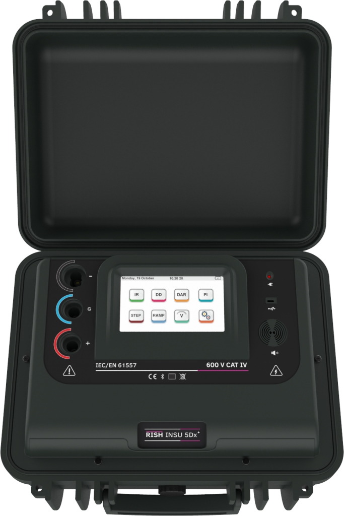
With Rish Insu 5Dx+, the step voltage test of insulation is conducted between the phase and body (frame) of the motor. This test is designed as a controlled over-voltage or proof test to provide an evaluation of the insulation system integrity. In Step Voltage test, as the name suggests, we apply the voltage in predefined steps. This test provides visual indication of how return current reacts to increased stepping of voltage. Voltage is stepped in user defined increments and duration.
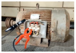
The test leads of Rish Insu 5Dx+ are connected to the phase terminal and body (frame) of the motor as illustrated in Fig 1:
Next, we will apply voltage to these terminals in user defined steps. Refer Fig 2. The value of steps are determined by the test operator by setting the step voltage and test time. In Rish Insu 5Dx+, step voltage is expressed as:
- Voltage Interval = Test voltage / 5
- Time interval = Test time / 5
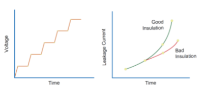
Thus, the voltage and the time interval is divided into 5 equal steps. With each step, the voltage applied across the two leads increases in specific voltage increments. As each step-in voltage occurs, if resistance remains the same then a proportional increase in current should be observed. If a symmetrical response is not observed, an insulation anomaly may exist or may be developing.
According to IEEE 95, If there are no significant differences in the value of Insulation resistance at each step, it indicates that the insulation is reliable and in healthy condition. However, if the resistance values at each step have differences beyond 25% between each , it indicates that the insulation requires inspection and reconditioning.
Thus, with the test conducted on the motor, it failed the above mentioned conditions and the root cause for electrical shock at the motor body was detected. There was a critical need to recondition or replace the insulation provided to the motor. With this test, we can understand the effect of cracks, mechanical damages and cavities in the device under test.
Other Applications
- Testing of Transformer Insulation resistance
- Insulation Testing of switchgear equipments in substations
- Insulation cable testing
Features
- Selectable short circuit current 1.2mA, 3mA and 6mA
- User selectable digital filters
- Noise Rejection 8 mA
- Operates on rechargeable Li-ion battery and Mains as well
- Bluetooth connectivity for data logging
- Touch screen TFT color display
- Audio Read-out
- Test voltage can be selected in steps of 10V from 100V to 1000V & in steps of 25V from 1000V to 5000V
- Measurement of DC and AC voltages from 20V ~ 600V
- Three programmable timers
- Insulation leakage current measurement
- PI, DAR, DD, Step voltage & Ramp Test