Overview
Induction motors are widely used in industries due to their robust construction and operation. The speed of an induction motor is not required to be the same always and this depends on the requirement of the process, unnecessary operation of an induction motor at full speeds demands more energy and hence speed control is essential.
Variable frequency drives or VFDs are now installed in almost every industry ranging from water pump applications to huge machine tool industries. Variable Frequency Drives can regulate the speed of a three-phase induction motor by converting three-phase AC line voltage to a quasi-sinusoidal pulse width modulated (PWM) waveform in which the frequency and voltage level can be varied.
Problem Statement
Variable Frequency Drives (VFDs) present unique challenges as both a source of Power Quality problems as well as being sensitive to incoming voltage quality. A frequent complaint with a troublesome VFD is the controller taking the drive offline due to unbalanced current drawn. This can be caused by high voltage unbalance from distribution, or from an impending failure in the VFD itself (which can then cause voltage unbalance). Separating the cause and effect of unbalanced voltage and current with a VFD is crucial towards eliminating the root cause of the complaint.
Introducing VFDs
Figure below shows the schematic of a 6 pulse VFD. The incoming 3 phase AC voltage is rectified by a series of diodes. This rectified voltage is smoothed into a DC voltage by filter capacitors, and sometimes inductance i.e a filter circuit. The DC bus capacitance also provides some energy storage for sag ride-through. The motor controller contains a microprocessor which switches the DC bus voltage into variable-width pulses that are applied to the motor through semiconductor switches (usually SCRs or IGBTs) in the inverter section. By precisely controlling with width of the pulses applied to the motor, the controller can adjust the motor speed

Effect of Voltage and current unbalance on VFD
Voltage unbalance is a sensitive issue for VFDs. Unequal delta line voltages cause differing currents to flow in the pairs of diode rectifiers, resulting in unequal diode heating. For a constant power, the diodes with the higher voltages applied end up heating more than the rest. The diode currents and temperatures are measured by the controller, and it will trip due to “excessive” current unbalance or diode temperature. For a temperature exceedance, when the system cools, the motor operates normally until the unbalance is enough to overheat a diode string again. If the current unbalance is near a threshold, a small change in voltage unbalance could cause frequent VFD trips.
Current unbalance may also be a sign of an impending diode failure – a common failure mode for a VFD. In this case, the current unbalance is due to a differing impedance during the conduction angle in a diode string, rather than incoming voltage unbalance. This unbalanced current can itself cause a localized voltage unbalance, making it difficult to separate cause from effect.
Solution
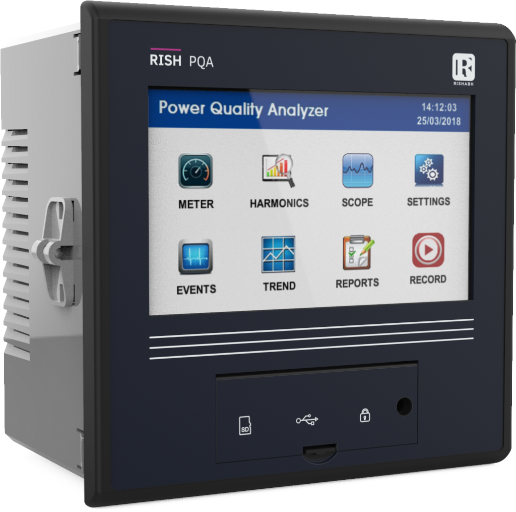
RiSH PQA is a compact state of art power quality analyzer designed for utilities, as well as for industrial & commercial customers. Rishabh’s Power quality analyser can measure multiple voltage and current related parameters that help understand the quality of power.
It can detect and measure voltage and current unbalance effectively as per EN 50160 with precise measuring capabilities. It measures the symmetrical components too.
Therefore by analyzing the recorded events and trends the unbalance in voltage and current can be detected. It therefore becomes essential to install such a device near VFD installations in order to avoid their failure by addressing power quality issues with the right mitigation tool.

Features
- Measures all basic electrical parameters like Voltage, Current, Power, Demand and Energy
- Energy Class 0.2S as per IEC 62053-22
- Measurement in all Four Quadrants
- 5″ TFT Display with 480×272 pixels resolution
- Real Time Representations of Three Phase Voltage and Current Waveform
- Harmonics measurement as per IEC 61000-4-7 Class II
- Per Phase Voltage, Current & Power Bar Graph Representation of up to 63rd Harmonic
- Power Configurator software to analyze recorded events and trends, and to generate excel report as per EN 50160